Micro MinimOSD KV Mod - Voltage shown is always 0.0V
« on: January 29, 2017, 11:59:16 am »
Hello everyone,

I am new to this forum and tried, up to now, to solve all issues on my FPV journey based on existing articles. However, I have reached a point, where I am stuck without assistance. According to what I found on the internet, everything is done right. Obviously, I must have missed something. Hopefully someone can help me :-)

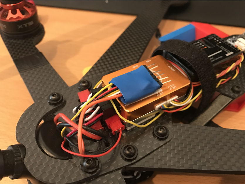
Some time ago I bought a drone, a Sky Hero Anakin Club Racer 6". I like its optical appearance :)


I did soon realize that something important is missing: Knowing the battery voltage. That's where my journey began. I added an OSD (MinimOPOSD v1.1) which worked fine, but it always showed 15.33V. Bought a 2nd one, same issue. Though, the board seems to be fine. I also tried a voltage divider (22 kOhm & 1,5 kOhm) to ensure the voltage output is between 0.0V and 1.1V. Based on my understanding of the board layout, that divider is unnecessary, as there are the necessary resistors already present on the v1.1 board. It did not work either. Overall, no progress. Time to restart.

I ordered an MinimOSD Micro KV Team Mod, which also is lots of smaller and less heavy. I configured it according to:
https://librepilot.atlassian.net/wiki/display/LPDOC/MinOPOSD+setup

Firmware: LP_MicroKvteam_CC3D_analog_inputs1708.hex
Chartset: Charset_1_3_0.mcm

Flight Controller: CC3D (dunno whether it's a revo, seems somehow customized in that orange box) with LibrePilot 15.09

Everything is wired according to the documentation, except for the battery ground. I made a direct connection between the Bat1-ground on the board to the CC3D connected ground. When the system is powered, I can measure the correct battery voltage between the Bat1 + and ground on the board. So that should be fine and saves a wire.

Here's an overview of my wiring:


And the final result:


The problems I still have are two, whereof at least one drives me crazy... :D

Firstly there's a slight ghosting of bright areas, which I deem not to be that distracting when the drone is in action. Ideas welcome :)

Secondly, the battery voltage shown to me through the OSD is always 0.0V. As mentioned above, I measured the correct voltage at these contacts.
What did I make wrong? Is there something else I can check?

It'ld be great if you could help me fixing this :)

Kindest regards
Fabian

f5soh

  • *****
  • 4572
    • LibrePilot
Re: Micro MinimOSD KV Mod - Voltage shown is always 0.0V
« Reply #1 on: January 29, 2017, 12:05:19 pm »
Nice setup.

Maybe try Bat2 input pads.

Re: Micro MinimOSD KV Mod - Voltage shown is always 0.0V
« Reply #2 on: January 29, 2017, 11:18:49 pm »
Simple, but brilliant. I had tried that with the MinimOSD 1.1 revision, which did not change anything. For the Micro mod, it works. Now it displays the correct voltage. Awesome =) Thx man!

Re: Micro MinimOSD KV Mod - Voltage shown is always 0.0V
« Reply #3 on: April 19, 2020, 11:23:00 am »

Everything is wired according to the documentation, except for the battery ground. I made a direct connection between the Bat1-ground on the board to the CC3D connected ground. When the system is powered, I can measure the correct battery voltage between the Bat1 + and ground on the board. So that should be fine and saves a wire.

Here's an overview of my wiring:


And the final result:


Guys I have a cc3d and soon I will receive the micro minimosd, my battery is connected to the pdb, but I did not understand how the guy in the post connected osd to the pdb with a single cable for detect the battery voltage.
Can you make me understand?
« Last Edit: April 19, 2020, 11:30:13 am by kekkosss »

Re: Micro MinimOSD KV Mod - Voltage shown is always 0.0V
« Reply #4 on: April 20, 2020, 09:54:39 am »
I am not an expert on OSD, but several things need to be correct:
- know which hardware board you have, example KV team mod
- know which pin on the OSD board you need / want to use for pack voltage and where that pin is actually located on the OSD board
- use the correct OSD board firmware for that board and compiled with or runtime configured with the correct option to make that pin into a voltage input
- before you hook it up, you probably need to research what the max voltage the OSD board input pin can take.  you may need to make a voltage divider resistor network (to scale down the voltage from the pack) and / or configure the correct offset (so zero volts reads zero) and scaling (so e.g. 12.0 volts reads 12.0 volts).  This resistor divider may already be built in to the OSD board.

When you connect the voltage to the OSD, then that part works the same as it does for any other FC firmware.

I think I have the same board as you have in your picture, but I connect the divided battery voltage to my Revo FC and it reads and scales the voltage and tells the OSD what voltage to display.  You can see that my OSD needs different firmware than yours because mine gets the voltage from what the Revo says rather than what some OSD input pin says.

The LibrePilot wiki has info on setting this up.  Have you read that?  Maybe here?
https://librepilot.atlassian.net/wiki/spaces/LPDOC/pages/91947115/MWOSD+Setup