It’s based on the original LP MinOPOSD code. I’ve been playing with it and adding or changing features for some time... The goal is to have in the OSD some vital kinds of information that would help me fly safer in FPV without distracting me during flight.
I believe the result had become useful enough to worth be shared. And I sincerely hope it to be of benefit to the LibrePilot project and community.
Because of program space limitations, I had to sacrifice some features in the original firmware that I’ve found not very useful to me in order to free code space and program new ones that I felt to be more beneficial. Like original MinOPOSD, the code can be compiled (compiler conditional defines) for different targets (CC3D or Revo, Multirotor or Plane) and features included or not.
New stuff:- Resettable OSD Home location. Initially set when GPS lock is obtained (like original MinOPOSD). Reset OSD (not FC!) Home Location by moving Radio Control (Mode2) right stick (Roll/Evelator) to upper right.
- Time-In-Flight: Time passed in ARMED state after the first throttle burst (takeoff). Time spent while gliding without throttle (wings firmware) counts!
- Flight-Time-Remaining: Estimated remaining time in the air, based on preset battery capacity, energy used (mAh) and time-in-flight (since takeoff). Does not count gliding without throttle (planes firmware).
- GPS lock can be 2D, 3D and DGPS (differential corrections: WAAS, EGNOS, etc.)
- 3D speed and Airspeed. Speed in the direction of flight (3d space; calculated from GPS speed and baro climb/descend rate). Airspeed (pitot tube) is displayed in planes firmware.
- Stall speed warning and alarm for planes. Stall speed threshold can be set in the OSD_JDL_Config tool. Airspeed indicator starts blinking when airspeed is less than 4km/h above the preset stall speed threshold. STALL ALARM is activated when airspeed is below the threshold.
- GPS altitude (ALT), Barometric Altitude-Above-Home (AAH) (BA) and GPS based Altitude-Above-Home (HA). BA & HA are reset in OSD automatically when OSD Home Location is set (or reset via RC right stick).
- Battery type (LiPo or Li-ion) selectable. Automatic cells count detection and LiHV detection for LiPo type (Li-ion type is fixed in firmware to 4 cells). Battery type can be configured in the OSD_JDL_Config tool and in the OSD setup menu. To enter OSD setup menu, toggle the switch for channel 7 to Panel3 position while disarmed.
- Configurable battery capacity in mAh. Setup it in the OSD_JDL_Config tool or in the OSD Setup menu. To enter OSD setup menu, toggle the switch for channel 7 to Panel3 position while disarmed.
- Remaining energy indicators (percents) (battery voltage and consumed energy based). Empiric Voltage-to-Remaining Capacity correction curves (different for LiPo and LiHV) are applied to battery voltage to obtain more realistic estimates for remaining battery capacity based on voltage.
- LTSR (LongTermSafetyRadius): Estimates how further (from the takeoff point) the pilot can fly before he has to turn back and return to takeoff location in stright line, with the remaining battery power. Uses the preset battery capacity, used energy (mAh) and total travelled distance since takeoff. Calculation is made with 20% battery capacity left in reserve.
- STSR (ShortTermSafetyRadius): Similar to LTSR but based on short term energy consumption and flight efficiency.
- Eff (Efficiency Estimation): Efficiency of motor flight (in milliWattHour/km). When throtte is off displays Estimated Gliding Distance before touching the ground (ground level is assumed to be the same as at the takeoff location; planes firmware). For Multirotors there is no glide distance estimation and the efficiency is displayed in Wh/km.
- Climb Rate. Multirotor firmwares display it in +/- m/s. Plane firmwares show it in m/min with different icons for climb or descend.
- Combined COMPASS HEADING and ROSE. Slightly altered appearance, also.
- HOME Direction and Distance are combined, too.
- MOD/ASWA indicator: Displays flight mode (ST1, ST2, MAN, RTB, PH, AC, etc.). MOD label is replaced with ASWA label, if ASWA (Always-Stabilize-When-Armed) is enabled and activated.
- Pre-arm and arming statuses: When not armed, OSD displays FC readiness to arm. DISARMED and icon “circle with ‘x’ inside reports “not ready to arm”, DISARMED and icon “circle with dot” inside signals the FC is ready to be armed, ARMING... appears while arming, obviously...

- WAYPOINT INFO (waypoint number, distance to it and Estimated-Time-Arrival) in RTB and PathPlan autonomous flight modes. In all other flight modes the waypoint info is hidden.
- Various warnings and alarms:
- Warning for low battery – when measured voltage falls below preset voltage (for a SINGLE CELL, eg. 3.55V) – can be configured in OSD_JDL_Config tool or through OSD setup menu.
- Warning for GoHomeNow! (LTSR < 0) or (STSR < 0)
- Warning for airspeed below stall speed threshold. STALL ALARM is displayed.
- Warning for low RSSI, low LQ (Link Quality). Hardcoded thresholds are RSSI < -84 / LQ < 105. These apply when OPLINK is used for RC control. There is also option to have OSD firmware that gets RSSI on a (PWM) RC channel (#10). The hardcoded RSSI warning threshold is set to -71dBm there.
- STAB and ATTI alarms, corresponding to the ones in GCS System Health. ATTI alarm display is supressed while FC is in armed state to avoid possible annoying announcement (during whole flight) of the erroneous ATTI alarm, caused by "THE BUG" in INS13.
- CPU WARNING, CPU CRITICAL, MEMORY LOW, STACK OVERFLOW – displayed by CC3D dedicated OSD firmware.
- OVERHEATING alarm, if external LM335z temperature sensors (connected to MinimOSD) are used to monitor ESC and Motor temperatures in the OSD. Hardcoded thresholds (in dedicated OSD firmware) are 60degC for ESC and 75degC for motor.
- Warnings display behavior is altered: When a warning appears, OSD switches immediately to Panel 1 and warning message flashes there (like in original MinOPOSD). Unlike it, if warning condition persists for more than approx. 3 seconds, OSD switches back to the panel that was active before alarm and the warning text continues to flash there until the warning condition is cleared.
Video mode might be set to PAL or NTSC like with original MinOPOSD. This is configurable in OSD_JDL_Config tool. I’ve not tested NTSC (I use PAL cams only) but it should work.
GPS coordinates (LAT, LON values) are displayed in
xx.xxxxx format, no letters. This is enough for an approx. a meter accuracy and saves space on the screen. Negative numbers for coordinates and these with three digits before decimal point are also displayed (can expand to the right).
Current and voltage sensors can be either connected to Revo FC (preferred!) or directly to MinimOSD board. Different precompiled OSD firmwares. If using voltage sensor only, connected to MinimOSD board, and NO current sensor,
disable it by setting “Current Sensor Amps Per Volt” and “Current Sensor Amps Offset” to zero (in OSD_JDL_Config tool or in the OSD Setup menu).
To disable LINK QUALITY / RSSI LOW alarms when using OSD without RSSI, just uncheck the "
RSSI & LinkQuality" fields on both Panel1 & Panel2 in OSD_JDL_Config tool!
There are some settings that are configurable in the original LP MinOPOSD but are hardcoded in this MinOPOSD JDL version, sorry for that... - OSD Toggle Channel is fixed to RC Channel 7 (Ch7)!
- All values are in metric system: m, km, m/s, km, h, Wh/km, etc.
I run all my UAVs on
LP “next” r735 based firmwares and the
MinOPOSD JDL code has UAVObject IDs for
r735 but I recall there are no changes in
r782 that will affect it and it should match with
r782 fine, too.
I’ve also included an option (compiler conditional define) to build the MinOPOSD JDL firmwares for
LP 16.09, respective UAVO IDs are there. However, I’ve not tested it recently. It should work, though...
MinOPOSD JDL requires a dedicated matching charset version that comes with OSD_JDL_Config, it should be uploaded to the MinimOSD the same way as with original LP MinOPOSD (through the OSD_JDL_Config tool).
Different
precompiled firmware HEX files for different
FC targets (Revo or CC3D),
UAV types (multirotors or planes) and / or
features supported can be also uploaded to the MinimOSD board the same way as with original LP MinOPOSD (through the OSD_JDL_Config tool).
Because of space limitations,
some firmwares are compiled
WITHOUT the ability to update charset! In such a case, if charset update is necessary:
- Upload any other firmware WITH update charset functionality.
- Do the charset update using this firmware.
- Finally, flash the desired firmware without charset update capability.
OSD can support up to three external LM335z temperature sensors (for ESC, Motor and Ambient air temperature monitoring), when battery voltage and current sensors are connected to Revo FC. Detailed how-to instructions shall be added later if there is interest.
Without extretnal LM335z sensors, the OSD displays baro sensor temperature.
All precompiled firmware HEX files, config tool and charset are available on github.
Some combinations were never tested in real as I don’t have such setups (like Multirotor + CC3D + Battery_on_OSD + Safety Radius&Eff), if you find any issues, let me know!
If anyone has interest in compiling the firmware himself, sources (OSD and Config tool) are there, too. OSD requires
Arduino 1.0.5-r2; the Config tool –
Microsoft Visual Studio 2010.
I’d like to emphasize that I had not made any efforts to make the changes to the source codes prettier, well commented and easier to read. It would be nice, but...

Precomplied firmware (LP 16.09 & LP “next” r.735+) HEX files features matrix| FW# | Multi rotor | Air plane | CC3D | Revo | Battery on OSD | Battery on Revo | Oplink Radio Control | RSSI on Ch10 | Charset Uploader | Safety Radius & Efficiency | Glide Est. | WP Info | Batt Type Select | LiHV detect | Stall Alarm |
| 01 | X | - | X | - | X | - | - | X | - | X | - | - | - | X | - |
| 02 | X | - | X | - | X | - | - | X | X | - | - | - | - | X | - |
| 03 | - | X | X | - | X | - | - | X | X | X | - | - | X (noBattCrv) | - | - |
| 04 | X | - | - | X | X | - | - | X | X | - | - | - | - | X | - |
| 05 | X | - | - | X | X | - | - | X | - | X (noEff) | - | - | - | X | - |
| 06 | X | - | - | X | X | - | X | - | - | X | - | - | - | X | - |
| 07 | X | - | - | X | - | X | - | X | X | X | - | - | - | X | - |
| 08 | X | - | - | X | - | X | - | X | X | X | - | X | - | X | - |
| 09 | X | - | - | X | - | X | X | - | X | X | - | X | - | X | - |
10 | X | - | - | X | - | X | X | - | - | X | - | X | - | X | - |
| 11 | - | X | - | X | - | X | - | X | - | X | X | X | X | - | X |
| 12 | - | X | - | X | - | X | X | - | X | X | X | X | - | - | X |
| 13 | - | X | - | X | - | X | X | - | - | X | X | X | X | X | X |
Charset .mcm file is located in "/ConfigTool_minOPOSD JDL/OSD Charset/" folder.HEX files are located in "/ConfigTool_minOPOSD JDL/OSD Firmwares/" folder: https://github.com/jdlilov/MinOPOSD-JDL/tree/main/ConfigTool_minOPOSD%20JDL/OSD%20Firmwares
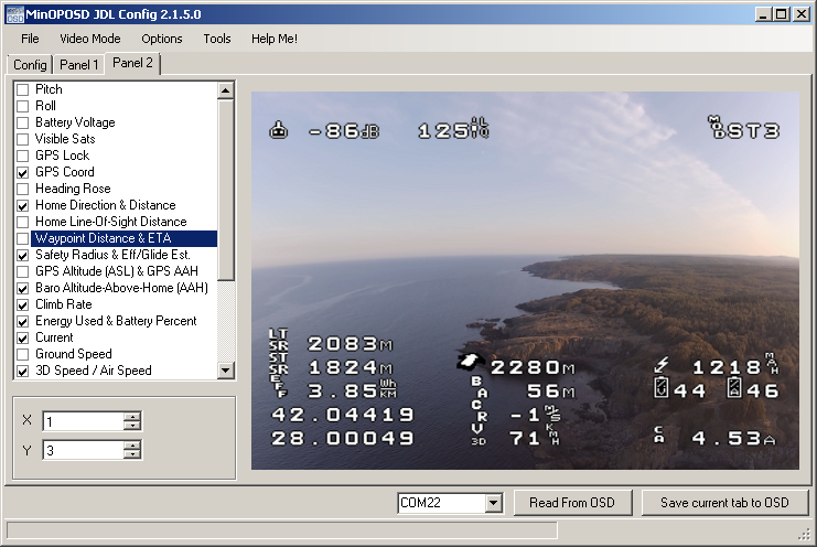
Config Tool Panels:


OSD DVR Samples:
GitHub Link: https://github.com/jdlilov/MinOPOSD-JDLDownload ZIP: https://github.com/jdlilov/MinOPOSD-JDL/archive/main.zip
P.S. (02 Dec 2020) Updated sources and precompiled firmwares (incl. LP 16.09 compatible) to version 2.53.